

This guide to retrofitting an Autoterm diesel auxiliary heater with an underfloor bracket in a VW T5 / T6 was created together with some of our installation partners and shows the use of our tigerexped installation kit with an Autoterm Air 2D (formerly Planar 2D) air heater.
Please note: If you install it yourself, you do so at your own risk; we cannot give any warranty for work we did not carry out ourselves. Text and photos are meant as inspiration. Experience with vehicle technology is absolutely necessary!
Installing an Auxiliary Heater in a VW T5 / T6 – What You Need
It’s actually quite simple: an installation kit including the heater, plus a few air duct parts from your friendly Volkswagen dealer. The VW parts take care of the warm air routing in the B-pillar, so the result looks as if it came straight from the factory. The ducts are also very well optimized for airflow, which makes this one of the quietest installations there is, with the least effort!
T5 / T6 Installation Kit – What Is Included
- An air heater with the original accessories, such as silencer, wiring harness and a control panel
- Our stainless steel underfloor heater bracket with bendable tabs for mounting the pump, silencer and cable
- An adapter for the warm air to connect to the VW air duct
- Air duct for the intake side and for connecting to the heater on the warm air side
- 60mm air inlet nozzle for the step, through which the air intake is realized. (The VW duct for the intake side does NOT fit)

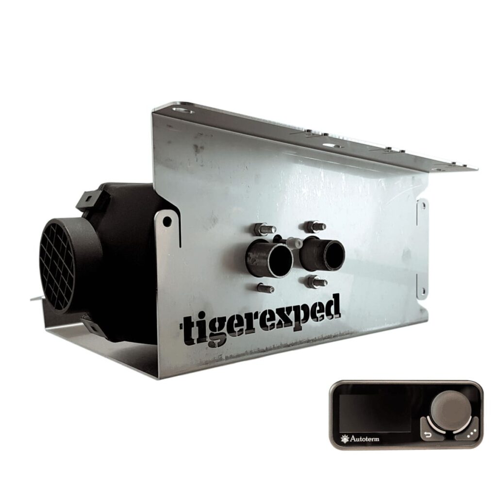
Installation kit for VW T5 / T6. With a 2 kW heater, underfloor mounting flange and Comfort Control panel:
What else you need
- M6 rivet nuts (4 are enough) with screws, M6x20 is sufficient
- Rivet nut tool
- Drill with a few drill bits
- A small body saw or angle grinder to enlarge the warm air opening in the B-pillar
- 60-63mm bi-metal hole saw for the air nozzle in the step, theoretically also doable with a body saw
- Optional for 4motion drivers: the stainless steel installation box for even more protection of the heater. It can be combined with our heater bracket with a few minor modifications (the front tab has to be removed), but it still does not turn it into a submarine!
- Optional: extension cable for the control panel to 7m. The original control panel can only be 1.8m from the heater, which may be too short depending on your interior layout.
- Optional: additional temperature sensor 5m. It can be used to separate the control panel from the temperature measuring point, or for example for a second heating zone in the pop-up roof
Installing the Heater
The position of the bracket is actually already determined by its shape and the pre-drilled holes in the body. Once you have removed the standard underbody panel, the installation location is visible behind the right front wheel, behind the step.
The underbody panel must be refitted after installing the heater! If it is no longer present, the heater has to be installed with the installation box.

Not all holes are necessarily present on every vehicle; these have to be added afterwards.
The bracket supports 6 screw points, but 4 will basically do. M6 rivet nuts have to be set, preferably in the middle of each slotted hole of the bracket, so there is enough play for the final alignment.


Then test-fit the bracket and check that it sits firmly. Careful, rivet nuts are not uncritical: they must sit tight, otherwise they spin and you have a lot of fun when (dis)assembling…

The heater can be screwed into the bracket outside the vehicle and then bolted under the vehicle in one piece together with the bracket.
Finally, bolt the whole package under the car with large washers or (as in the right picture here) special screws with a large head. With that, the heater itself is done.


The Heater Add-On Parts
The stainless steel exhaust silencer is included in the kit, as is a small angle bracket, which we can now use for mounting. Conveniently, there is already a hole further back in the side member, which we can fit with another rivet nut. The silencer is mounted lengthwise here and connected to the heater with the exhaust pipe. You can also wrap this pipe with the supplied insulation.


The underfloor bracket has special tabs that can be bent down slightly. The intake silencer can easily be attached here with cable ties. As you can see: the opening of the intake silencer does NOT point in the direction of travel.


On the left side of the bracket there is another single tab, which we bend outward by 90° with pliers. The rubber holder for the fuel pump can be attached here!


Connecting the Fuel Supply
Option 1: T-Piece in the Line to the Supplementary Heater
Those whose vehicle has a supplementary heater can count themselves lucky. It traditionally sits on the driver side and already has its own connection to the tank. So we take a T-piece and tap exactly this line.
This installation guide shows a T5 / T6 without an AdBlue tank. Installation can differ on vehicles with an AdBlue tank.

Several lines run here, so please really trace back from the supplementary heater first, so you do not cut the wrong line. Since a pro was at work here, the transparent fuel line in the picture has already been covered with a black protective hose. One reason, among others: with a bit of skill you can pull the line through the cross member and so get very elegantly from the driver side back to the passenger side, where our new heater is already longing for fuel!
This installation guide shows a T5 / T6 without an AdBlue tank. Installation can differ on vehicles with an AdBlue tank.


Option 2: Fuel Pickup Tube in the Tank
The tank has to be drained so that the fuel sender can be removed. This is because the fuel pickup tube has to be inserted from the INSIDE through the hole drilled into the tank.


The pickup tube can be positioned right on the raised area next to the fuel sender. The fuel hose is routed forward along the original fuel line and fixed with cable ties.


… and because it is so nice: routed through the cross member again to its destination.

Option 3: Fuel Pickup Tube in the Fuel Sender
If you have the tank out anyway, you can of course also choose to insert the fuel pickup tube directly into the fuel sender. By the way, this is the approach used by other big suppliers.
But be careful: take care when drilling, because a fuel sender costs real money!
Careful, the fuel sender is fitted with springs and is under pressure. The spring travel has to be taken into account when cutting the pickup tube to length.

Fuel Pump
Now that we finally have fuel, the pump can go in its place. The outlet points to the right (the side with the electrical connection!) and is connected to the heater in an elegant curve.
The connector can now also be assembled (make sure the pins click cleanly into the connector housing, polarity does NOT matter!) and then routed in the same curve as the fuel line over to the right edge of the bracket.
The tabs that were bent down earlier for the intake silencer serve once again as fixing points for cable ties.


Routing the Wiring Harness
Since the wiring harness for the pump and power supply is quite long, you can, for example, “store” it rolled up and fixed with cable ties on the heater. If you are brave, you can of course shorten it here, but this may cause trouble in a warranty case.
Conveniently, there is a body plug in the floor panel where you can pass both the control panel cable and the power supply cable into the vehicle interior. Depending on how far away you want the control panel, the extension mentioned above makes good sense here. Since the additional temperature sensor would also have to be connected directly to the heater, it is a candidate for this routing. Its cable is 5m long as standard.


Warm Air Routing via the B-Pillar
The cut-out for the B-pillar is not present from the factory. The upper trim has a curve that in theory fits the B-pillar in only one single place, but it is not entirely trivial and there is no drilling template. So please: work step by step!
Insert the cable into the B-pillar from below, make a hole at the top, then work forward slowly until everything fits.


The plastic trim itself MAY contain very fine pressing marks that mark the cut-out exactly, but apparently this is not always the case. If the cut-outs are not visible in the trim, you first have to place the air distributor on the B-pillar and, again, work out the cut-outs step by step. It can be fiddly, but the result is all the nicer for it.


To connect the heater to the VW duct, the adapter included in the installation kit is inserted into the rubber part from VW.
With a short piece of 60mm air duct (also included in the kit), the outlet side of the heater can then be connected directly and very cleanly.
The main advantage of this solution is that the enlarged cross-section of the VW duct automatically reduces the flow speed of the warm air, which has a very positive effect on noise.


Inside the vehicle, all that is left is to fit the trim and click in the vent grilles – done!

Air Intake in the Step
The intake side is relatively trivial. First you remove the step trim and drill the hole for the supplied inlet nozzle. When you refit the trim, it is also clear where the hole in the body behind it has to go. From behind, all you then need is a nice curve made of the supplied 60mm air duct and the intake side is done!


After installing the heater, the underbody panel still fits under the car exactly like the original, and the ground clearance is not reduced. The exhaust silencer may still need a short piece of exhaust hose so that it can stick out of the underbody panel comfortably and without touching anything. You have to fiddle that into place depending on the mounting location – but a clean solution should be easy to find here!
Wiring in the Interior
Last but not least, the cables in the interior have to be routed cleanly, which everyone has to do themselves based on their personal interior fit-out. Just 3 remarks on that:
- Please fuse the heater properly. If the starter battery is used, you should definitely monitor the voltage, because the heater’s undervoltage threshold of 10.7V is very low – depending on the weather, you may then no longer be able to start the engine!
- Depending on the control panel, you should also think about its position: if you choose an installation kit with Autoterm Comfort Control or the OLED control panel, a temperature sensor is built into the control panel, so you should choose the mounting position sensibly.
UPDATE Feb 2026: The OLED control panel has been discontinued in favor of the Comfort Control. - If an additional temperature sensor is used, you have 5m of cable available. If you choose the PU-5 rotary controller (now called Simple Control Panel) as the control panel, you need the external temperature sensor to enable temperature control.
- If you use the Autoterm Comfort Control, you can set up a second heating zone (for example in the pop-up roof), because you can switch between different sensors on the display.
Done! If you did everything right, it looks like this in the end… Robert from @lustaufnatur captured this on his T5 with a thermal imaging camera – looks great! Many thanks for that 😉

With that, happy heating, and always remember: if you do not trust yourself to do the installation, please contact one of our installation partners, where you can also get the heater directly.
Thanks to Nico Lüttschwager, Christoph Meier (SyncroExplorer) and Nic Böttcher (Zweistein) for some of the detail photos.
Did this help you? It might help your friends too, so share the post in your groups or as a message:
These articles about installing an auxiliary heater might also interest you:


