
If a motorhome solar system consists of several modules, they can be connected to each other in different ways.
We explain the background behind the various recommendations and why both options can have their merits – “it depends.”
Series and Parallel Wiring – What’s the Difference?
Parallel wiring:
With parallel wiring, the solar modules are connected plus to plus and minus to minus. With this type of wiring,
- the current adds up,
- the voltage stays the same.

Series wiring:
If the solar modules are wired in series, they are connected plus to minus. Current and voltage behave exactly the opposite way compared to parallel wiring:
- The current stays the same,
- the voltage adds up.

Which Option Is Better?
Claiming across the board that one wiring type or the other is better would be making it a little too easy. But don’t worry: there are very clear criteria that will tell you reliably which option is the right one in your case.
One of the most important points is the type of solar modules. If you use modules whose performance reflects the current state of the art, parallel wiring has a number of advantages.
Why that is the case, and the technical background, is what you’ll find out below.
How the Charge Controller Behaves with Different Solar Modules
As mentioned, with series wiring the voltages coming from the modules add up. This total voltage is then present at the input of the charge controller.
If you use powerful solar modules with a high open-circuit voltage and wire them in series, the total voltage quickly exceeds the voltage rating of the charge controller.
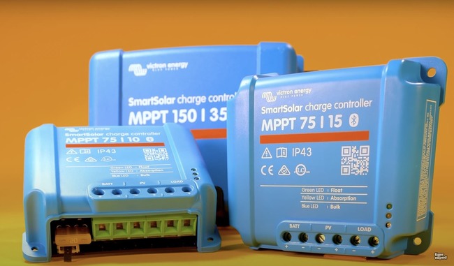
Common charge controllers handle up to 100, 150 or 250 volts of input voltage, but the purchase price of devices rated for more than 100 volts is significantly higher.
With some of our black tiger solar modules, for example, the voltage rating of a 100 volt charge controller is already exceeded from the second module on. Here, around or even over 50V per module can be present. A charge controller with 100V input voltage must not be used here for series wiring.
Sure, you can always go bigger, so you could use a charge controller that can work with a higher input voltage, e.g. 150V. But these controllers also work with currents of 35A at the output, and that’s where it gets really expensive. In principle, you invest a small fortune to make series wiring possible, which in combination with these modules offers you very little advantage.
Raising the Input Voltage by Connecting Modules – Why It Still Makes Sense
If you use solar modules with open-circuit voltages of perhaps just 18 – 20 volts, it makes sense to wire a small number of them in series (up to 100V input voltage) to increase the incoming voltage.
Keep in mind that, because solar modules have a negative temperature coefficient, the voltage keeps rising as temperatures fall. The voltage rises above the value given on the datasheet when the module is colder than 25°C.
Unfortunately, the opposite effect exists as well: the voltage drops at temperatures above 25 degrees – typical cell temperatures in summer are 60 degrees Celsius and more.
Choosing the Right Module for Your Battery
For a solar charge controller to start up at all and begin charging the battery from solar, the voltage coming from the module(s) and present at the controller must be at least 3-5 volts above the current battery voltage (depending on the solar controller). Otherwise, the controller stays off.
Example:
If the current battery voltage is 13 volts, the solar panel must deliver at least 18 volts before anything happens at all.
If you work with a 24 volt system and the battery voltage is 26 volts, we even need 31 volts from the solar panel for charging to start. With a solar module that can only deliver 21 volts maximum, the battery would never be charged … or at least not before it has already been damaged by deep discharge. In this case, you would have to use series wiring to raise the voltage and be able to start charging.
By contrast, a single module with a high open-circuit voltage (e.g. 50 volts) can start charging right away, even in a 24 volt system.
The voltage that matters to us in the system, however, is not the current system voltage but the battery’s end-of-charge voltage that has to be reached. You’ll find it on the battery’s datasheet. For LiFePo batteries, look for the value for absorption voltage. This is the highest voltage occurring in the system, and the one the charge controller must ever be able to set.
To be able to charge at full power right to the end (up to 100% state of charge of the battery), the module voltage has to be 3 – 5 volts above the absorption voltage.
The voltage at which a solar module delivers full power can also be found on the datasheet. It is called the nominal voltage or Umpp, where mpp stands for maximum power point.
To take the temperature effects described above into account, multiply the value from the datasheet by 0.9.
Rule of thumb 1: Choosing the module to match the battery
The nominal voltage (Umpp), multiplied by 0.9, must be 3 – 5 volts higher than the battery’s absorption voltage / end-of-charge voltage. This also ensures quick full charging of the battery on hot days.
And What About the Open-Circuit Voltage?
The open-circuit voltage is the voltage present in a solar module when no load is connected. It is the maximum voltage that can come from the module, and is therefore the criterion for choosing the solar controller.
The open-circuit voltage is given as Uoc in volts (Voc) and can be found on the solar module’s datasheet. oc stands for open circuit, i.e. the open-terminal voltage.
Rule of thumb 2: Choosing the controller to match the module
When choosing the right controller, you should add a margin of at least 10% to the open-circuit voltage (Voc) so you’re prepared for cold winter days, too.
What Else Do You Need the High Voltage For?
Extending the Charging Period
As we have just seen, the voltage coming from the solar module must always be at least 5 volts above battery voltage for us to be able to charge at all.
When the sun rises in the morning, the voltage climbs relatively quickly the more the sun shows itself. If the module delivers a higher overall voltage in full sun, we also have a sufficiently high voltage early on to start charging.
It’s the same at the end of the day. The sun sets and gets weaker and weaker, and our voltage falls – with solar modules that have a high voltage overall, however, it stays high enough for charging for longer.
The high voltage therefore extends the time of day that can be used for generating power.
But:
Voltage isn’t everything. It has to be said quite clearly that when the sun gets high and enough voltage is present, this doesn’t automatically mean you end up with a notable amount of storable power. It depends on several factors. The voltage rises quite quickly, even with weak sun / a poor angle of incidence …
How big the benefit of the extended time window really is in practice can’t be answered here with solid average values.
The gain on this point tends to be rather small, though.

Less Power Loss with Partial Shading
Let’s take a look at the internal wiring of a solar module, because the individual cells also have to be connected somehow.
In our black tiger solar modules, we use so-called half or third cells. The familiar square shape with the cut corners is effectively sliced through. A single cell then has only half the power, but the voltage is increased due to an internal series connection – the more cells or half/third cells are connected in series, the higher the voltage.
One row includes one of the halves or one of the thirds. The other parts are connected in their own separate so-called strings.
Advantage of Individual Strings
For example, if a series connection consists of 40 cells (or parts of a cell) with approx. 52Voc, this series connection can be divided into several segments. The segments can in turn be bridged with a so-called bypass diode.
That means:
If one cell is shaded, its row – that is, the half or third of the module concerned – drops out. Since the other parts are decoupled from this string, however, they can keep working independently.
The voltage does drop, but even if only 25 of 50V remain, that is still enough for charging in a 12V system.
With solar modules that have a high open-circuit voltage, you therefore still get along well even under unfavorable conditions and in a single configuration, and can charge your batteries in most situations.
Advantages of Parallel Wiring
More Modules Can Be Connected
Since parallel wiring doesn’t exceed the controller’s voltage rating, more modules can be connected to one controller with parallel wiring.
Modules with Different Currents Can Be Used
If the parallel-wired solar system is to be expanded or a damaged module replaced after some time, modules with a different current can be used as well. With parallel wiring, differing currents are simply added up and together form the total current.
All that matters is to make sure the voltage is the same! This even allows solar bags to be used as a top-up.
Disadvantage of Parallel Wiring
Parallel wiring involves somewhat more complex cabling. In addition, the higher current results in a larger required cable cross-section, which in turn means higher material costs.
Compared to a larger controller, or several controllers, with series wiring, however, this is manageable.
Advantages of Series Wiring
Less Power Loss with Partial Shading
A small calculation example, based on the facts we have already learned:
If half of a solar module drops out due to shading, its voltage falls by half. With series wiring, the MPPT controller detects the reduction in total voltage and simply keeps working with it.
With parallel wiring, on the other hand, only the current adds up, not the voltage. If half a module now drops out due to partial shading, it can happen (with modules with a low open-circuit voltage, e.g. 18 volts) that the power loss affects the entire module and not just half, because its voltage is now only 9 volts.
If the voltage of the second module also halves due to partial shading, no current comes in at all anymore, because the remaining 18 volts are no longer above the controller’s “start-up threshold.”
As we can see, however, this advantage is theoretical if you decide from the outset to use good components and the modules have a correspondingly high open-circuit voltage.
MPP Tracking with Parallel Wiring and Partial Shading
Even if the voltage is still high enough for the system to run: with parallel wiring and partial shading, we have two modules with different voltages. As a result, the MPPT controller will settle on an average – somewhere between the voltage of the unshaded and that of the shaded panel. So neither the optimum of one panel nor of the other.
That costs us some maximum power and therefore some yield.
This problem doesn’t exist with series wiring.

What does an MPPT controller actually do
MPPT = Maximum Power Point Tracking.
The controller constantly looks for the best operating point and adjusts its input voltage so that the product of voltage and current gives the greatest power.
MPPT controllers are therefore more efficient than PWM controllers, which act almost like a direct connection between battery and solar system and pull the solar system’s voltage down almost to battery level. Under some circumstances, quite a few valuable watts remain unused with a PWM controller.
Disadvantage of Series Wiring
The biggest disadvantage of series wiring, as we already established at the very beginning, is the disproportionately high price of controllers that can work with a high input voltage. Since a high open-circuit voltage of the solar modules is desirable, though, that often is the end of the line with just a few modules – you can’t connect the desired number of modules together at a good price-performance ratio.
Series or Parallel Wiring? Pros and Cons in a Nutshell
Advantages of series wiring
- Possibly lower power loss with partial shading and use of an MPPT charge controller (with modules with a low open-circuit voltage).
- Thinner, simpler cabling
Disadvantages of series wiring
- Charge controllers for series wiring of several modules are disproportionately expensive from 100V input voltage, without you benefiting from major advantages.
- Only modules with the same current can be used.
Advantages of parallel wiring
- The system can be expanded with modules or solar bags of the same voltage.
- Modules with different power ratings can be used.
- The system keeps working even if one module fails completely.
Disadvantages of parallel wiring
- Possible slight power loss with partial shading.
Advantages of solar modules with a high open-circuit voltage
- Even with just one module (or one left over after damage / defects), the system can work – even with 24V systems.
- Longer charging window, since the voltage stays high enough for longer in the morning and evening.
- If one of the solar module’s internal strings drops out due to partial shading, the remaining voltage is still high enough for the system to charge the batteries.
Conclusion on Series or Parallel Wiring of Solar Modules
You can’t say across the board “one connection type is good and the other is bad.” Several factors decide in the end which connection type is best for you and your vehicle.
If you’re unsure, or generally need help putting together an electrical system that suits your travel needs: Contact our technicians, who will be happy to help you with no obligation.
Did this help? Feel free to share the article with friends and like-minded people to support them with their camper projects!
These topics might interest you too: