
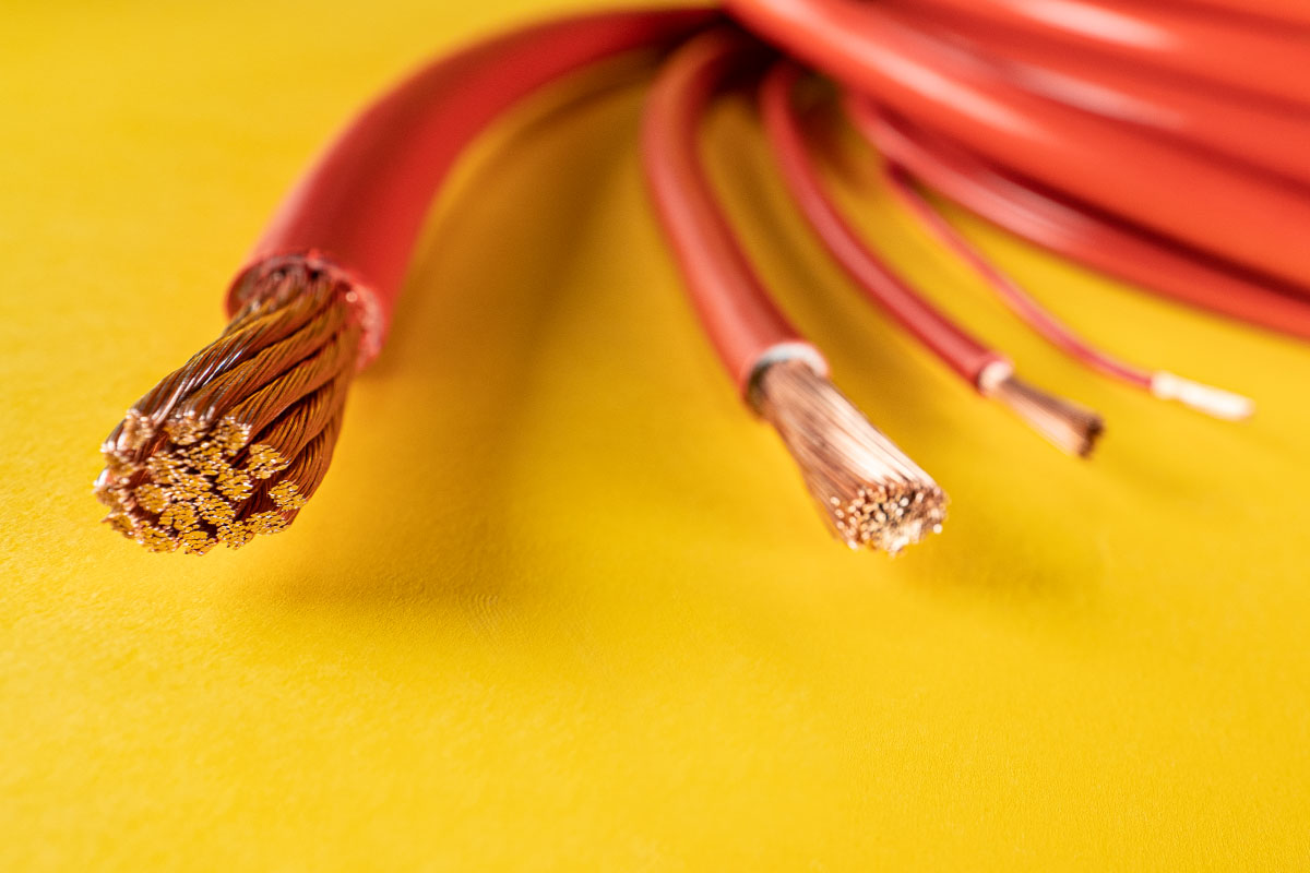
Whether you are running power for devices and sockets in your camper or at home: calculating the right cable cross-section is immensely important. On the one hand, with copper prices rising, needlessly thick cables cost real money and add weight; on the other hand, a cable that is too thin is a safety risk.
Here you learn to calculate it yourself which cable cross-section fits exactly, and to understand why – and for what reasons it is important to be able to do this yourself despite the abundance of online calculators. We also look at how the temperature and installation method of your cables affect the current-carrying capacity of a conductor cross-section.
For this we provide helpful tables that you can view in PDF format as well as download and print.
And don’t worry: it is all not as difficult as it sounds.
One note up front:
Before wiring the electrical devices of your system, check their arrangement once more and how sensibly the cables can be routed. Often people start by mounting the biggest devices first, according to the available space, and the small ones then fill the remaining gaps.
An arrangement by functional groups makes much more sense here, as often becomes apparent during wiring.
Is your system not complete yet?
We offer you advice by phone, including a requirements calculation for your personal use case, and put together the necessary components from the solar panel to the fuse accordingly – so that not only the cable cross-section fits, but also the components match each other and your system works reliably and safely.
Find out more here and request your non-binding personal consultation.
Calculating Cable Cross-Section – The Voltage Drop
Basically, a cable is a resistor. The electrons flowing through the copper from the positive to the negative terminal create friction and cannot flow through the cable completely unhindered. The longer and thinner the cable, the greater this friction – so the resistance increases with the length and decreases with the cross-section of the cable.
The resistance does two things: First, the cable heats up. Second, a small part of the applied voltage is lost. This lost voltage is called the voltage drop.
The voltage drop has to be limited. Not least, the function of many devices depends on a certain voltage level being maintained.
For sensitive devices the voltage drop should be limited to a maximum of 2% (e.g. chargers, solar charge controllers without their own voltage sense cable). For non-critical devices, such as a lamp or a water pump, you can accept up to 4% voltage drop.
Voltage Drop vs. Cable Length
So the cable must be thick enough to limit the voltage drop to a certain level. However, overly thick cables have two real drawbacks: they hit your wallet hard, and they are damn hard to route.
There is only one way to be able to use a thinner cable: you have to keep the required cable length as short as possible. The more “juice” a particular consumer draws, the more important it is to place it as close to the battery as possible. A powerful 3000 watt inverter, for example, already needs a thick cable close to the battery, say 70 mm². Placed far from the battery, the cable would theoretically have to get EVEN thicker, which leads to absurd cable sizes and cable lugs that you can hardly screw on anymore, etc. In practice, such applications should absolutely be avoided.
REMEMBER:
The higher the power consumption of the consumer, the closer its installation location should be to the batteries.
The Power of the Consumer
The third component we have to take into account for calculating the conductor cross-section, besides voltage drop and cable length, is (as already hinted) the power of the consumer.
Power is given in watts (W).
In many cases you can simply read the power off the device’s rating plate and insert it into the corresponding formula – we will get to that in a moment. First, though, let’s clarify how to work out the watts if the figure is NOT printed on the device.
Example Calculation: USB Socket
Let’s now walk through an example with a task that any of us may face at some point: installing a USB socket.
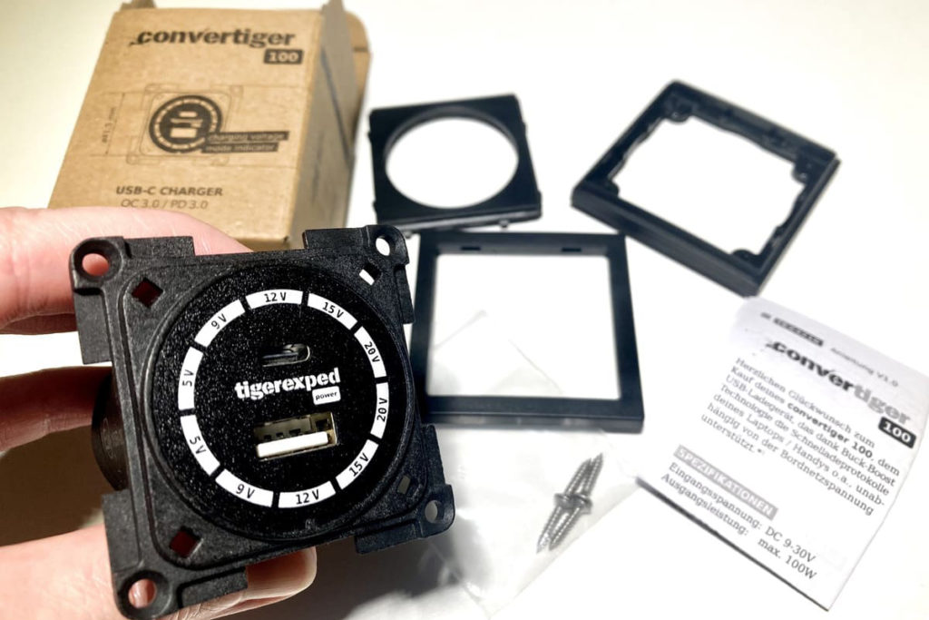
Our example is a powerful USB socket with two ports that can charge your devices simultaneously at 2 amps each .

Let’s get started:
The packaging or rating plate says:
5 volts (V) and 2 x 2 amps (A)
Everyone has probably heard the formula for calculating power at some point. It is
Power (P) = Voltage (U) x Current (I)
With our numbers for the USB socket, the calculation is therefore
P = 5 x (2 + 2) = 20 W
At full load, the socket would thus draw 20 watts.
TIP: Include a safety margin.
Add a safety margin on top that can compensate for interference effects and a efficiency that is not 100 percent. We allow 20% here.
So we assume a total of 24 watts, because
20 W x 1,2 = 24 W
What Voltage to Use in a 12 V System
Before we insert our numbers into the formula to calculate the cable cross-section, we have to deal with the fact that even in a 12 volt system you cannot simply always calculate with 12 volts.
Rule of thumb:
You calculate with the lowest voltage that can occur in the system, because at the lowest voltage the current flowing through the cable is highest.
So how low can the voltage get in a camper with a 12V system? That depends on the battery technology in use. A normal lead-acid battery should not be discharged below 10.7V to avoid permanent damage. For this reason, most undervoltage protection systems also switch off at this value (depending on settings and battery type).
How much current flows in a 12V system with a consumer power draw of 24 watts: to work this out, we divide power (watts) by voltage (volts). This calculation makes it easy to see that a higher voltage automatically results in a lower current, so it is exactly right to calculate the maximum flowing current by starting from the lowest voltage. In our case that is
24 W : 10.7 V = 2.24 amps
Factoring in the Voltage Drop
As established above, every cable is a resistor on which we lose a bit of voltage. Let’s assume we do not want to allow more than 2% voltage drop. The calculation in this case is
2% of 10.7V = 0.214V
This value goes straight into our calculation.
Factoring in the Cable Length
The cable length is always made up of the way there and the way back from the battery to the consumer. If the USB socket is installed 3 m from the battery, we need 3 m of positive and 3 m of negative cable, and both go into the calculation. In the formula for the right cable cross-section for our USB socket we therefore use a value of 6 m for the cable length.
A special case is connecting a positive cable from the battery to the consumer while the negative is returned via a sheet-metal body. The body is an extremely thick conductor, so we assume a voltage drop of zero. In this case only the length of the positive cable is used for the calculation.
Conductivity of the Cable
The conductor material also plays a role, as there are cables made of aluminum, copper or iron, which all have different conductivity. As a rule, though, when wiring electrical consumers in your camper you will use copper cables, because anything else really has no place in a travel vehicle conversion.
That simplifies things, as we can always work with one and the same number. The value for copper can be found in the corresponding conductivity tables and is 58 Siemens (the value may vary slightly between tables, but if you simply remember the number 58 you are well advised). The 58 applies to all copper cables you will ever want to install in your life.
Important note on buying copper cable:
Copper cable is not the same as copper cable. It should be finely stranded wire. When buying, look for the designations FLY or FLR-Y as an indication of the current automotive standard.
Here you will find our extensive cable range with high-quality FLY and FLRY cables and installation accessories.
Short Summary of Our Determined Values
Cable length: 6 m
Current: 2.24 A
Voltage drop: 0.214 V
Conductivity: 58 Siemens
Calculating Cable Cross-Section – The Formula
With our collected values, let’s now come to the “world formula of the cable cross-section”: it is
and for our USB socket thus
Watch Out When Using a Calculator
Don’t forget to divide the result from the upper half of the fraction by the entire denominator, otherwise you will get a wrong result!
So first calculate 6 x 2.24 and press = to store the result. Then press “divided by” and enter the calculation 58 x 0.214 in brackets to get the correct value.
Rounding Up the Cable Cross-Section
According to our result we need a cable with a cross-section of 1.082 mm² to connect the USB socket safely and with the desired power, but without spending too much.
However, 1.082 mm² is not a common cable size and cannot be found in any shop. With such results it is entirely proper to round up to the next common cable size. In our example that would be a cable size of 1.5 mm².
Summary of the Calculation
Even though we have written a lot by now, calculating the cable cross-section boils down to two very simple steps.
Two numbers are worth remembering, as they always stay the same – namely 58 and 0.214. The product of these two, 12.412, is easy to remember, and you then simply always calculate cable length x current divided by 12.412 and you have the cable cross-section.
Cable Cross-Section Calculator
If you are now wondering why you should remember all this at all, since there are hundreds of online cable cross-section calculators:
There are many calculators online, but they are not necessarily designed for this use case. If you are not able to check for yourself what an automatic calculator found on the internet does and whether it produces a suitable result, you should simply not rely on it.
Of course you can use an online calculator and keep using it once it has earned your trust. At the start, check the result in one or two spot checks to judge whether the calculator is suitable for your purposes.
Something else online calculators do not do: put the result into a sensible relation to the installation method and current-carrying capacity of your cables. We do this in the sections that follow. A basic understanding of the technology, which can decide on safety in your travel vehicle, is therefore better than any online configurator.
Update, October 2026:
Cable and Fuse Calculator for Campers – by tigerexped
The tigerexped cable cross-section and fuse calculator for exactly your use case in the camper is here. It also takes the installation method into account and shows what your cable can actually withstand as a result.
Even so, we stand by this: build up solid basic knowledge of the topic here, it will help you again and again and make you more confident in handling your camper technology.
Calculating Cable Cross-Section – Video Explanation
So much for the steps so far – explained once more by tiger Martin.
Don’t forget to look at the correction steps right below!
Correction Steps After Calculating the Cable Cross-Section
Don’t worry: the calculation we have made is fine, and the 1.5 mm² cable is right for the USB socket.
There are, however, two more steps you should take into account.
Temperature vs. Current-Carrying Capacity
Temperature has a major influence on how many amps of current a cable can safely carry. To find out whether we are on the safe side with the cable cross-section calculated above, we first look at a current-carrying capacity table that gives us the information we need. You can view and download the complete table here.
For a 1.5 mm² cable, the table gives a current-carrying capacity of 24A at 30°C and 17A at 50°C. With our calculated maximum current of 2.24 A we are therefore well within the green zone.
Cable Cross-Section vs. Cable Installation Method
It actually makes a big difference whether a cable runs on its own somewhere or is installed together with several others in a cable duct. Cables get warm, and when they are bundled into a thick bundle, it naturally gets harder, especially for the inner ones, to get rid of the heat.
The rule:
The thicker the bundle, the bigger the temperature problem – logical.
In your camper it certainly makes sense to bundle several cables together and route them neatly through the vehicle. How this affects the current-carrying capacity of our 1.5 mm² cable can be seen in another table, which you will also find under the download link further above.
In the table we find the information that, e.g., with eight cables in a shared cable duct, the current-carrying capacity of each individual conductor is reduced by a factor of 0.5. That means a cable that runs in a shared cable duct with seven others can only carry half as much current as if it were installed freely.
In our example with the USB socket this means, however: even at 50°C ambient temperature the cable could still run in a bundle of eight in the cable duct, because on its own it still manages 17 A at this temperature, and half of 17 is 8.5, which is still much more than our maximum of 2.24 amps.
Since the effects of installation method and ambient temperature are by no means negligible, let’s look at another example.
Example: Cable Cross-Section for a Powerful Inverter
Large inverters, for example, such as you need for induction cooking or running a powerful hair dryer, can easily draw 180 amps. Such currents are already quite a load in a 12 volt system and also come with considerable heat generation.
Taking into account a voltage drop of max. 2%, the formula gives us a required cable of 14.5 mm², which we round up to 16 mm², the next available size.
A look at the current-carrying capacity table now reveals the following:
A 16 mm² cable may only be loaded with a maximum of 98 amps at 30°C ambient temperature. That is FAR below the 180 we need. If the ambient temperature rises further, the load capacity will of course drop even more. So the cable cross-section calculated with the formula above is absolutely not enough.
According to the table, for 180 amps of current at 30°C ambient temperature we have to install a cable cross-section of at least 50 mm². With a maximum current-carrying capacity of 198 amps at 30 degrees, though, there is not much temperature headroom left, which is why in this case we definitely advise going one better and using the next larger cable. We are now at a cross-section of 70 mm², which handles 245 amps at a temperature of 30 degrees. Only now are we at a safe value.
70mm² Cable – in the Cable Duct?
Once your calculations have arrived at cable sizes like this, there is no need to look at the installation method table. A cable of this cross-section must not be installed together with other cables, so that they do not heat each other up and reduce the current-carrying capacity.
Correction Steps – When They Are Probably Necessary
Cables dissipate heat through their surface. But because we want to keep cables that are supposed to carry a lot of current as short as possible, this becomes a disadvantage for heat dissipation.
So, especially with powerful consumers that are installed close to the battery to avoid a large voltage drop, remember to look at the two tables after calculating the cable cross-section. Only they can tell you beyond doubt whether the cable is still sufficient from these points of view as well and a fire hazard can thus be ruled out.
Correction Steps – Explained in the Video by tiger Martin
Summary, Step by Step:
1. Download the two tables – if you have not done so above, here is the link again.
2. Calculate the cable cross-section as discussed in the first part of the article.
3. Check the calculated cross-section – does it still hold up with the chosen installation method and at 50° C?
Calculating Cable Cross-Section – Conclusion
Calculating the cable cross-section is not hard at all, and usually one single small formula gets you there. And precisely because it is so simple: only trust online calculators once you have checked at least once or twice with spot checks that they are not calculating nonsense.
For powerful consumers, also be sure to keep in mind that the formula for calculating the cable cross-section may only be half the truth. A look at the current-carrying capacity table and taking the installation method into account are mandatory here to avoid the risk of cable fires.
Attention:
So that in case of doubt the fuse really blows and the cable holds:
- Read the article on fuse sizing and
- download our overview table for choosing fuse sizes for high ambient temperatures.
These articles from our electrical topic area might also interest you:


Did this article on calculating the cable cross-section help you? Show it to friends and like-minded people too, so they can benefit as well: